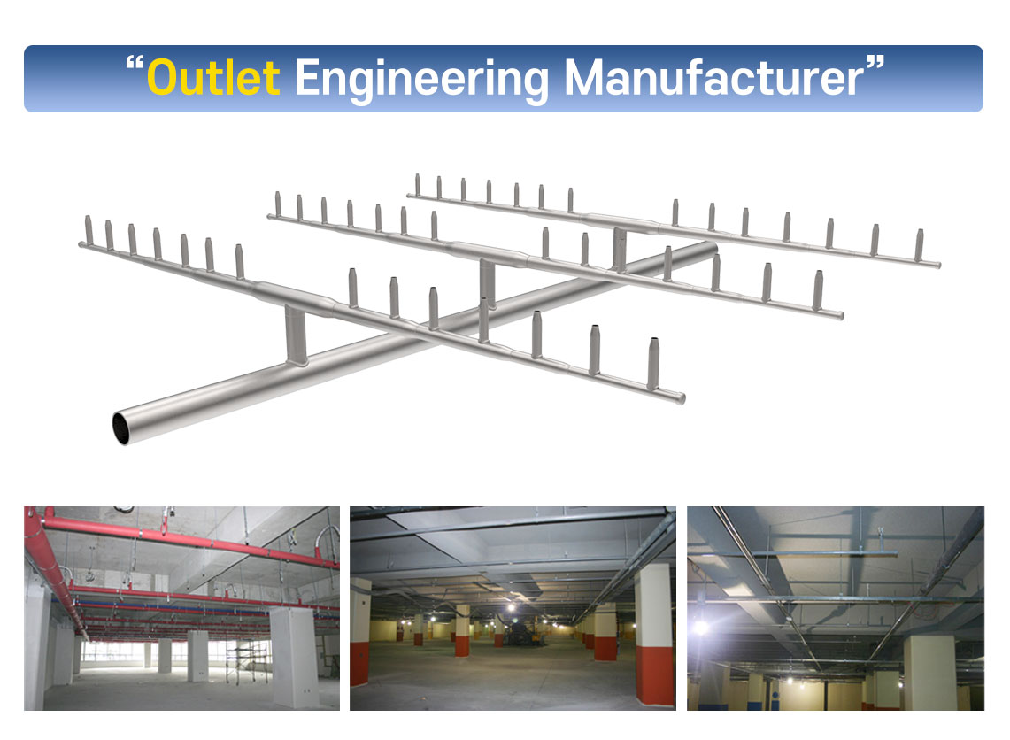
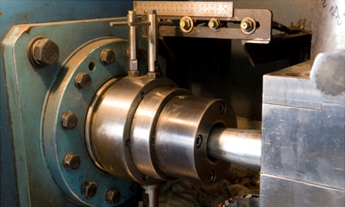
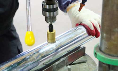
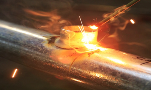
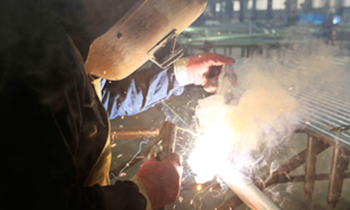
The sprinkler equipment, which is the most basic Suppression System against fire, can function properly only when branch piping, newly-constructed piping, pipe joints for Suppression System, head, etc. are organically connected by cutting, perforating and welding.


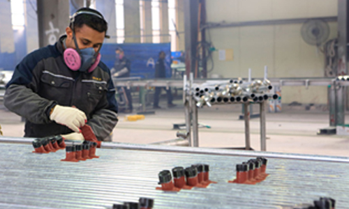
PLS Suppression System pipe outlet engineering does not artificially widen the pipe, but by welding the cold-forged Suppression System pipe outlet after perforating the pipe, it has sufficient strength, corrosion resistance and heat resistance.


This outlet engineering method is widely used in advanced countries such as in the U.S.

Characteristics of Suppression System Piping using the pipe outlet

The outlet engineering method of the Suppression System is a manufacturing technology of Suppression System piping that can significantly improve the work environment with the decrease of the construction period and cost saving by directly connecting branch pipes to the main pipe, not using parts such as existing TEE.

Merits of the Suppression System Piping using the Pipe Outlet

  • Reduction of construction period by improving the work efficiency through factory manufacturing and on-site module assembly 
  • Reduction of labor cost by reducing skilled workers and on-site manpower due to factory manufacturing and on-site module assembly 
  • Improving the work environment when installing on site by minimizing contacts with other processes 
  • Reduction of material costs due to the reduction of pipe scraps and reduction of used parts 
  • Possible to manufacture on site and easy to respond to repair and design change

Suppression System Piping (Production Capacity)


Material ITEM PLS
Carbon Steel

Stainless Stee

Firefighting Piping 20,000 Heads


Materials of Suppression System Piping

The engineering method of the Suppression System outlet is a manufacturing technology of Suppression System piping that can significantly improve the work environment with the decrease of the construction period and cost saving by directly connecting branch pipes to the main pipe, not using parts such as existing TEE.

KS KS D 3507 (Steel pipe for piping)
KS D 3537 (Galvanized steel pipe for water supply)
KS D 3562(Carbon steel pipe for pressure piping)
KS D 3564 (Carbon steel pipe for high-pressure piping)
KS D 3570 (Carbon steel pipe for high-temperature piping)
KS D 3573 (Ally steel pipe for piping)
KS D 3576 (Stainless steel pipe for piping)
ASTM ASTM A-53 GR. A or B
ASTM A106-B
ASTM A312-TP304

Suppression System Piping Material


Equipment Name Unit Specification Manufacturer
CNC1 Lathe 1 11kW, Chuck:200 mm 2020x1655x1820(H) WIA
CNC2 Lathe 1 11kW, Chuck:200 mm 2020x1655x1820(H)) WIA
CNC3 Lathe 1 11kW(7.5HP), Chuck:8” 2020x1655x1620(H) WIA
Shot Blast 1 500kg 2600*3500*3600H Myeongjin Industry
Lathe 1 Bed swing 630, Cross Slide Swing 380, Center Distance 2,000 Hwacheon
Compressor 1 MAWP:13bar/189psi, Mass:655kg ATLAS COPCO
Cutter (Band Saw) 1 25A150A 1.1/0.75kW 380V 60Hz Tera Tech
Mobile Band Saw 1 AC220V, 60Hz , 15A~200A FEMI
Perforator 1 Drill:23mm Steel:14/Cast Iron:16mm
3 phase 1/2HP*6P
Hinam
Marker (horizontal) 1 AC220V, 60Hz PSA Marking
Marker (verticality) 1 AC220V, 60Hz PSA Marking


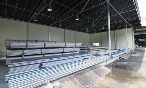
Step 1 : Receiving materials & storage

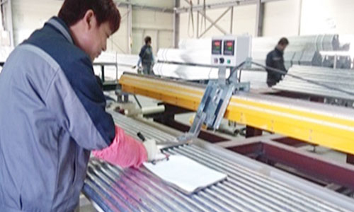
Step 2 : Marking

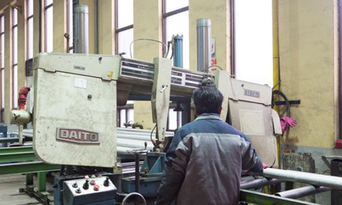
Step 3 : Cutting

Step 4 : Shaft Pipe

Step 5 : Perforation

Step 6 : Tack Welding

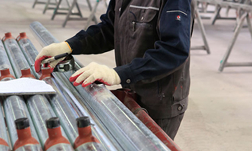
Step 7 : Welding

Step 8 : Coating

Step 9 : Product Inspection & Package

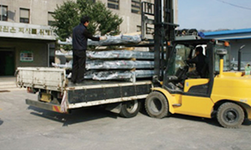
Step 10 : Shipping

I am text block. Click edit button to change this text. Lorem ipsum dolor sit amet, consectetur adipiscing elit. Ut elit tellus, luctus nec ullamcorper mattis, pulvinar dapibus leo.